
                   mu * I

        B   =   --------------

                  2 * pi * d
In SI units the magnetic field is measured in tesla when I is in amperes and d is in meters. The quantity mu is a constant known as the permeability of free space and has the assigned value of
                                          tesla * meter

        mu  =  4 * pi * 10-7     ------------------------                                                                       (1)

                                                amp
If a long, straight conductor carrying
current I is placed in a magnetic field of strength B, the
conductor will experience a force whose magnitude on a length L
of the conductor is given by
F = I * L * B * sin(theta) (2)where theta is the angle between the current and field directions. The force F has the units of newtons if B is measured in teslas, I in amperes, and L in meters.
Now, if two long, parallel conductors carrying currents I and I' are separated by a distance d, each will experience a force due to the magnetic field set up by the other. Combining Eqns. 1 and 2 for the case of parallel wires (theta = 90 degrees), the following result is obtained:
                 mu * I * I' * L

        F   =   -----------------                                                                                                         (3)

                    2 * pi * d
The forces exerted on the two conductors are equal in magnitude and oppositely directed, as required by Newton's Third Law. If the currents are in the same direction, the conductors experience an attractive force, while oppositely directed currents will produce a repulsive force. This equation is valid only for infinitely long conductors. However, if the separation d between the conductors is very much less than the length of either conductor, then the error in the equation is negligible. If the currents in the two conductors are equal (I = I'), then Eqn. 4 becomes
                   mu * I2 * L          2x10⁻⁷ * I2 * L

        F   =   -----------------     =       -----------------                                                                            (4)

                    2 * pi * d                     d
This last result is used to define the unit of current, the ampere. Formally,
`` one ampere is that current which, if present in each of two parallel conductors of infinite length and separated by a distance of one meter in a vacuum, causes each conductor to experience a force of exactly 2 x 10⁻⁷ newton per meter of length. ''At the National Institute of Science and Technology, primary measurements of current are made using a current balance. In a current balance, the conductors form part of an arm of a sensitive balance and the force between them, when they carry a current, is counterbalanced by a weight m added to the other arm. Current balance measurements are used to calibrate secondary standards (ammeters) which are more convenient to use for current measurements. When at static equilibrium, the moveable conductor feels a gravitational force (mg) equal to the repulsive magnetic force. The result is
m = C * I2 (5)where the constant C is given by
                   mu * L

        C   =   --------------                                                                                                                 (6)

                2 * pi * g * d
It is clear that the plot of m vs. I2 should be a straight line passing through the origin, having a slope equal to C.
You should not need to adjust the apparatus, but the following information is provided in case it is necessary.
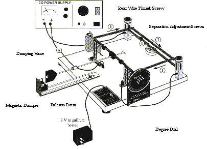
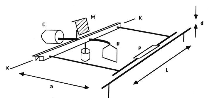
The current balance is shown in Fig. 1. The balance has four terminal posts, one near each corner. In setting up the circuit, the two posts at one side should be joined by a fairly long wire. The other two posts are used to connect the balance in the circuit (Fig. 2). It is important that the lead wires connected to the binding posts of the balance leave at right angles to the side of conductors which are part of the frame. Voltage control is achieved by use of a step-down 6-volt transformer. The control knob on the carbon block resistor used for current variations should be loosened to increase the resistance to a maximum before power is applied. The apparatus is leveled by removing the frame from the balance and adjusting the leveling screw under the base. The frame should be replaced with the knife edges (K) positioned on the bearing posts so that the pins on the beam-lift engage easily. Operation of the beam-lift will place the beam in the same position each time the lift is raised. During this experiment, it is preferable to disturb the balance beam as little as possible. The alignment of the conductors is done by placing a coin or other mass on the pan (P) and adjusting the appropriate thumbscrews; however, the beam lift must be operated after each adjustment to be sure that the knife edges are always in the same place. After the balance has been leveled and aligned, the laser and scale should be positioned so that the laser's reflection appears near the middle of the scale.

Figure 1. Schematic Diagram of Current Balance
Next, place the 100-mg weight gently onto the pan at the center of the upper bar. The bar should sink down on top of the lower bar and stay there. As the upper bar sinks, the mirror tilts and the reflected laser spot sinks, too. After the upper bar has settled down, measure the position of the laser spot on the scale again. It should be a few centimeters lower.
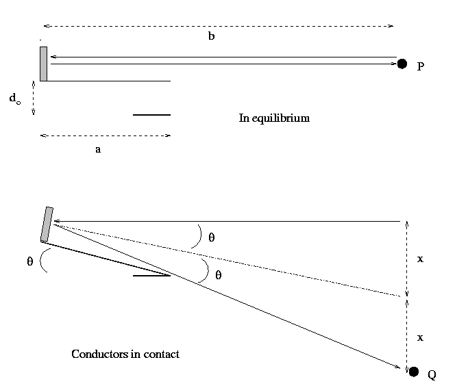
The separation d0 between the upper and lower bars when there is no weight in the pan (the equilibrium separation) is given by the relation
                                   D * a

                         d0 =  ----------

                                   2 * b
where D is the difference in scale readings, a is the distance from knife edge to the center of the upper conductor, and b is the distance from the back of the mirror to the scale. For a derivation of this equation, see below.
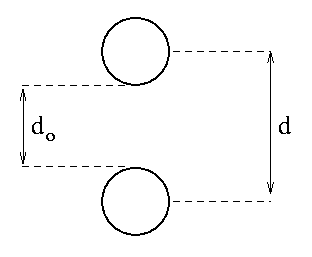
When the apparatus is set up, the value of b should be at least 150 cm, and preferably 175-180 cm. The quantity d discussed in the Theory section is the center-to-center distance between the conductors. You should use a vernier caliper to determine the diameter of each conductor, and this average diameter is added to d0 to obtain a value for d.
                          (diameter of upper bar) + (diameter of lower bar)

      d  =  d0  +   ---------------------------------------------------------------------------------------

                                                                     2

Figure 3. End-on Detail of Parallel Current-Carrying Bars
Also measure L, the (conducting) length
of the upper bar. Once you have determined the equilibrium separation,
d0, and the values for d and L, you should
make no further mechanical adjustments to the current balance.
Try to be gentle while removing and placing
masses on the pan; do not touch or disturb the balance beam in any way.
If the beam is jarred inadvertently, make sure you break the circuit before
attempting to set it back into place. You may use the beam lift to reposition
the beam. If you must do this, be sure to check the equilibrium reading
on the telescope with the current turned off, making sure it agrees with
the previous equilibrium value. At no time during the experiment should
the current be allowed to exceed 10 amps.

We start off with the upper bar and lower bar some distance d0 apart. When the laser beam reflects from the mirror, it strikes the scale at some point P.
Then we weigh down the upper bar so that it
tilts by an angle theta and comes into contact with the lower bar.
The distance from the knife edges to the end of the upper bar is a,
so
d0
tan (theta) = ----
a
The mirror attached to the upper bar shares
this tilt. The laser beam strikes the mirror at an angle theta and
is reflected at an angle theta, so the light is deflected by a total
angle 2 * theta and now strikes the scale at point Q. The distance
from the mirror to the scale on which the laser shines is b, so
we can figure out the distance D between P (the equilibrium location
of the laser spot) and Q (the location of the spot when the bars touch).
                      x    =  b * tan(theta)


                                        d0

                           =   b *  ----

                                        a


                      D    =  distance from P to Q


                           =  2 * x


                                     b

                           =  2 * --- *  d0

                                      a
If we rearrange to solve for the distance do between the conductors in the equilibrium position, we find
                                  D * a

                       d0   =  -------

                                  2 * b
Last modified by MWR 5/2/1999